Expansion Boards
What is an "expansion board"?
We use the term "expansion board" when referring to adding additional Arduino boards when a single Raspberry Pi (your main system) does not meet all of your needs.


- Why would I need an expansion board?
- What expansion boards can I use for Voltsec?
- How do I add an expansion board?
- What protocol should I select?
- Protocol: I2C
- Protocol: "USB / Serial-232" - using a USB cable
- Protocol: "USB / Serial-232" - hooking up via Serial
- Protocol: "USB / Serial-232" - long run
- Protocol: "USB / Serial-485"
- Programming Your Arduino Board
Why would I need an expansion board?
There are several scenarios where you may want to add expansion boards to your system Say for instance that you have a lot of sensors and you use up all the available pins on the Raspberry Pi. Adding an additional "expation board", you can increase the number of pins you have access to.
Another scenario would be a detached garage. Perhaps you want to hook several sensors and relays up in a garage, and it wouldn't be feasable to run multiple security wires between the two locations. By running a single cat5e wire, you could add an Adruino board in your garage, and attach and your garage sensors to that board.
What expansion boards can I use for Voltsec?
Voltsec currently supports three different types of boards. These boards are all easily available from retailers such as Amazon or eBay.


How do I add an expansion board?
The first step is that you will need to login to your account on our website (or in the Voltsec mobile app) and add a new board.
You will be asked to enter the following fields:
-
Description
Enter a unique name to help you identify the board when adding sensors. -
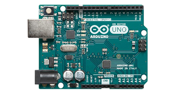
Board Type
Select the model of the Arduino board that you will be using (Mega, Uno or Nano). -
Protocol
The "Protocol" is the method by which the expansion board (Arduino) will comminucate with your main system board (Raspberry Pi). The option you will select depends on how far away the boards are going to be and what you want to hookup. Scroll down to see an explanation of each option. -
Address
Once you enter the board and the protocol, you will need to select the "address" of this board. It doesn't matter what address you select - but you will have to enter the same address when you program your expansion board (more on this below).
What protocol should I select?
The protocol you will select will depend on where you will be placing your expansion board. If you are putting the Arduino board right next to your main system and want to just connect the two boards together via USB, select "USB / Serial-RS232". You could also use 2 jumper wires and connect the boards together via I2C. You should not use I2C for long runs.
Protocol: I2C
I2C is a very stable means of comminucation and is relatively simple to hookup. You can use three jumper wires to connect the two boards together.

- Blue wire: Connected the GPIO-2 (SDA) pin on the Raspberry Pi to D20 (SDA) on the Arduino Mega
- Pink wire: Connected the GPIO-3 (SCL) pin on the Raspberry Pi to D21 (SCL) on the Arduino Mega
- Black wire: Connected to GND (ground)

- Blue wire: Connected the GPIO-2 (SDA) pin on the Raspberry Pi to A4 (SDA) on the Arduino Uno
- Pink wire: Connected the GPIO-3 (SCL) pin on the Raspberry Pi to A5 (SCL) on the Arduino Uno
- Black wire: Connected to GND (ground)

- Blue wire: Connected the GPIO-2 (SDA) pin on the Raspberry Pi to A4 (SDA) on the Arduino Nano
- Pink wire: Connected the GPIO-3 (SCL) pin on the Raspberry Pi to A5 (SCL) on the Arduino Nano
- Black wire: Connected to GND (ground)
Protocol: "USB / Serial-232" - using a USB cable
The simplest way to connect two boards together is to simply connect them via a USB cable. Simply use the correct USB cable to connect the Arduino board to one of the four USB ports on the Raspberry Pi (it doesn't matter which port).
Note: Each model of Arduino boards require a different type of USB cable.
Protocol: "USB / Serial-232" - hooking up via Serial
You can also use jumper wires (as opposed to the USB cable) to hook the two boards up as serial. The following diagrams show you how you can connect the two boards together using three jumper wires.

- Blue wire: Connected the GPIO-14 (TXD) pin on the Raspberry Pi to D19 (RX1) on the Arduino Mega
- Pink wire: Connected the GPIO-15 (RXD) pin on the Raspberry Pi to D18 (TX1) on the Arduino Mega
- Black wire: Connected to GND (ground)

- Blue wire: Connected the GPIO-14 (TXD) pin on the Raspberry Pi to D0 (RX0) on the Arduino Uno
- Pink wire: Connected the GPIO-15 (RXD) pin on the Raspberry Pi to D1 (TX0) on the Arduino Uno
- Black wire: Connected to GND (ground)

- Blue wire: Connected the GPIO-14 (TXD) pin on the Raspberry Pi to D0 (RX0) on the Arduino Nano
- Pink wire: Connected the GPIO-15 (RXD) pin on the Raspberry Pi to D1 (TX1) on the Arduino Nano
- Black wire: Connected to GND (ground)
Protocol: "USB / Serial-232" - long run
Select Serial-232 if you need to make a long run. The easiest way to accomplish this is by using two RS-422 boards, available here or here.


- Blue wire (Pi Side): Connected the GPIO-15 (RXD) pin to RXD on an RS-422 Module
- Pink wire (Pi Side): Connected the GPIO-14 (TXD) pin to TXD on an RS-422 Module
- Red wire (Pi Side): Connected to VCC (5V)
- Black wire (Pi Side): Connected to GND (ground)
- Blue wire (Arduino Side): Connected the D19 (RX1) pin to RXD on an RS-422 Module
- Pink wire (Arduino Side): Connected the D18 (TX1) pin to TXD on an RS-422 Module
- Red wire (Arduino Side): Connected to VCC (5V)
- Black wire (Arduino Side): Connected to GND (ground)

- Blue wire (Pi Side): Connected the GPIO-15 (RXD) pin to RXD on an RS-422 Module
- Pink wire (Pi Side): Connected the GPIO-14 (TXD) pin to TXD on an RS-422 Module
- Red wire (Pi Side): Connected to VCC (5V)
- Black wire (Pi Side): Connected to GND (ground)
- Blue wire (Arduino Side): Connected the D0 (RX0) pin to RXD on an RS-422 Module
- Pink wire (Arduino Side): Connected the D1 (TX0) pin to TXD on an RS-422 Module
- Red wire (Arduino Side): Connected to VCC (5V)
- Black wire (Arduino Side): Connected to GND (ground)

- Blue wire (Pi Side): Connected the GPIO-15 (RXD) pin to RXD on an RS-422 Module
- Pink wire (Pi Side): Connected the GPIO-14 (TXD) pin to TXD on an RS-422 Module
- Red wire (Pi Side): Connected to VCC (5V)
- Black wire (Pi Side): Connected to GND (ground)
- Blue wire (Arduino Side): Connected the D0 (RX0) pin to RXD on an RS-422 Module
- Pink wire (Arduino Side): Connected the D1 (TX1) pin to TXD on an RS-422 Module
- Red wire (Arduino Side): Connected to VCC (5V)
- Black wire (Arduino Side): Connected to GND (ground)
Protocol: "USB / Serial-485"
Serial Rs-485 is more complicated and is only recommended for expert installations. Please contact us for additional support in setting up an expansion board using RS-485.
Programming Your Arduino Board
Now that you have setup the board via the website or mobile app, the Arduino board still needs to be programmed. Programming the board will install the Voltsec expansion software on the board, and also tell the board how to communicate with the main system board.
The Arduino boards need to be programmed using the Voltsec Control Panel (available in our downloads section).
For more information about how to program your Arduino board, see our "expansion boards" section of our software installation turotial.